
Description
Specifications
| CM4 SOCKET | suitable for all variants of Compute Module 4 |
|---|---|
| NETWORKING | Gigabit Ethernet RJ45 connector, 100M Ethernet RJ45 connector |
| CONNECTOR | Isolated RS485 × 4, Power screw terminal × 1 |
| USB | USB 2.0 Type A × 2 |
| CAMERA | MIPI CSI-2 port × 2 (15pin 1.0mm FPC connector) |
| VIDEO | HDMI port × 1, supports 4K 30fps output |
| RTC | Real-time clock with battery socket and ability to wake Compute Module 4 |
| STORAGE | MicroSD card socket for Compute Module 4 Lite (without eMMC) variants |
| FAN HEADER | allows speed adjustment, 5V |
| INDICATOR | Power indicator × 1, CM4 status indicator × 1, User LED × 2, RS485 communication indicator × 8 |
| POWER INPUT | 7-36V |
| DIMENSIONS | 93.6 × 108.8mm |
Connecting With Compute Module 4
Standard CM4 Socket And Suitable For All Variants Of Compute Module 4

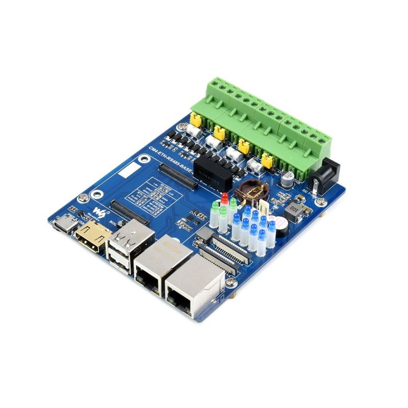
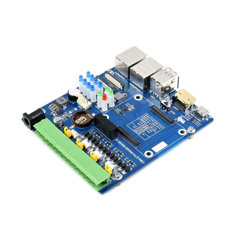
More Rich Interfaces
Various Interfaces Including: Dual ETH / RS485 / CSI / FAN / HDMI / Micro SD / USB

Application Examples
Suitable For Raspberry Pi Applications Requiring Multi-Channel RS485 Communication Or Other Industrial Context

for reference only, CM4, display, and cameras are NOT included.
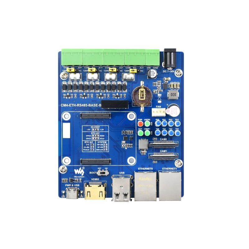
What’s On Board

- CM4 socket
suitable for all variants of Compute Module 4 - IO-VREF
Set the CM4 IO logic level as 3.3V (default) or 1.8V - RTC-12C: 12C bus selection for RTC
Can choose SDA0 & SCLO (default) or GPIO2 & GPIO3 - RTC INT: RTC interrupt pin select
D16: Use GPIO16 to receive interrupt signal when RTC interruption (default)
GL-EN: CM4 powerdown on RTC interruption
PI-RUN: CM4 will reboot on RTC interruption - SYSTEM: System function configuration
WP-DIS: Prevent EEPROM from being overwritten
BT-DIS: Disable Bluetooth function, for CM4 with antenna variant ONLY
WIFI-DIS: Disable WiFi function, for CM4 with antenna variant ONLY - Boot
ON: CM4 will be booted from USB-C interface
OFF: CM4 will be booted from eMMC or Micro SD card - PWR & USB
When the BOOT switch is “ON”, can be used as the USB programming or DC power supply port
When the BOOT switch is “OFF”, only used as the DC power supply port - HDMI0
HDMI port, supports 4K 30fps output - USB
2x USB 2.0, for connecting sorts of USB devices - ETHERNET0
CM4 original Gigabit RJ45 ETH - ETHERNET1
USB extended 100M ETH - CAM0 & CAM1
2x MIPI CSI camera ports - Buzzer
GPIO22 control
- FAN
4-pin FAN header, only supports 5V FAN, allows PWM speed adjustment (GPIO18 control, speed measurement is not supported) - RTC battery socket
Supports CR1220 button cell - RS485 TX/RX indicator
TXn: TX indicator for channel n
RXn: RX indicator for channel n - User LED
USER0: GPIO20 control
USER1: GPIO26 control - PWR
Raspberry Pi power indicator - ACT
Raspberry Pi working status indicator - DC 7~36V
DC power supply interface - Power input terminal
DC power supply terminal, supports 7~36V wide range power input - RS485 terminal
4 x Isolated RS485 terminal with a spacing of 5.08mm - Jumper
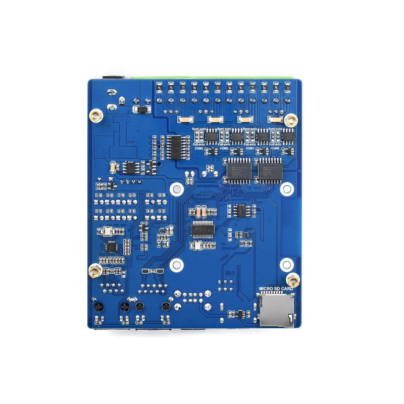
120R Balance Resistor Selection Jumper - RS485 operating mode selection
Full-auto: automatic mode, easy for program operation but the load capacity is weak
Semi-auto: semi-automatic mode, which requires manual TX/RX switching, with high reliability and strong load capacity - Encryption chip
ATSHA204 encryption chip, providing multiple encryption to ensure data security and reliability - Micro SD card slot
for connecting a Micro SD card with pre-burnt image (Lite variant ONLY)
Outline Dimensions


Reviews
There are no reviews yet.